Maxitronix/10in1/7: Difference between revisions
Jump to navigation
Jump to search
(Created page with "This is project 7/10 for my Maxitronix 10in1. I asked about how to probe this circuit over here: https://www.eevblog.com/forum/beginners/how-to-measure-am-broadcast-circuit-with-oscilloscope/ I learned a few things: # All four probes on my scope have their ground leads connected to each other (there is only one ground) # To avoid potential problems for beginners it is best to only connect one ground lead (the others can be left unattached) # I should use my probes...") |
No edit summary |
||
| (3 intermediate revisions by the same user not shown) | |||
| Line 10: | Line 10: | ||
# In 1x mode the resistance is 1MΩ and the capacitance is 100pF | # In 1x mode the resistance is 1MΩ and the capacitance is 100pF | ||
# In 10x mode the resistance is 10MΩ and the capacitance is 10pF | # In 10x mode the resistance is 10MΩ and the capacitance is 10pF | ||
When connecting this circuit to the oscilloscope connect to the collector of the NPN transistor to see the "modulated" signal (which is sent to the radio) and to see the "signal" (which is either "off" or "on") connect to the positive power terminal. | |||
In a radio receiver, a [https://en.wikipedia.org/wiki/Beat_frequency_oscillator beat frequency oscillator] or BFO is a dedicated oscillator used to create an audio frequency signal from Morse code radiotelegraphy ([https://en.wikipedia.org/wiki/Continuous_wave CW]) transmissions to make them audible. | |||
From [https://www.eevblog.com/forum/beginners/how-to-measure-am-broadcast-circuit-with-oscilloscope/msg5392505/#msg5392505 here]: | |||
[[File:CW.PNG]] | |||
[[File:MCW.PNG]] | |||
Latest revision as of 14:04, 15 March 2024
This is project 7/10 for my Maxitronix 10in1.
I asked about how to probe this circuit over here: https://www.eevblog.com/forum/beginners/how-to-measure-am-broadcast-circuit-with-oscilloscope/
I learned a few things:
- All four probes on my scope have their ground leads connected to each other (there is only one ground)
- To avoid potential problems for beginners it is best to only connect one ground lead (the others can be left unattached)
- I should use my probes in 10x mode, not 1x mode
- In 1x mode the resistance is 1MΩ and the capacitance is 100pF
- In 10x mode the resistance is 10MΩ and the capacitance is 10pF
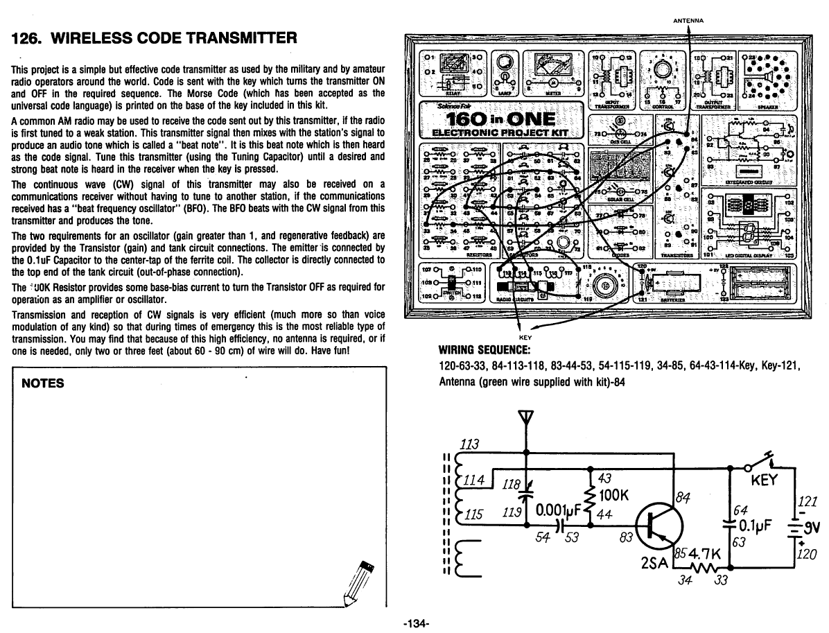
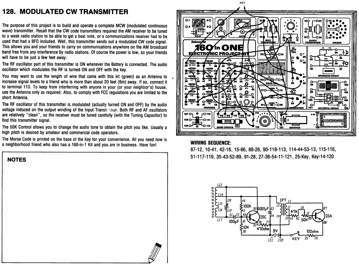
When connecting this circuit to the oscilloscope connect to the collector of the NPN transistor to see the "modulated" signal (which is sent to the radio) and to see the "signal" (which is either "off" or "on") connect to the positive power terminal.
In a radio receiver, a beat frequency oscillator or BFO is a dedicated oscillator used to create an audio frequency signal from Morse code radiotelegraphy (CW) transmissions to make them audible.
From here:

